I regularly use a 22LR pistol at close range for certain utilitarian purposes. It's convenient and in theory, it should be adequate. Let's be realistic though. It's always at night, and I permanently suck with a pistol. Something with more energy and better tolerance on shot placement would be nice, but a long 20ga is the other extreme. It's prohibitively awkward in a doorway, and at close range, it's a bit excessive. A short 410 would be nice, but that's not what's at hand here. I do have a Marlin 1894 in 44 Magnum. So the wheels start turning.
 |
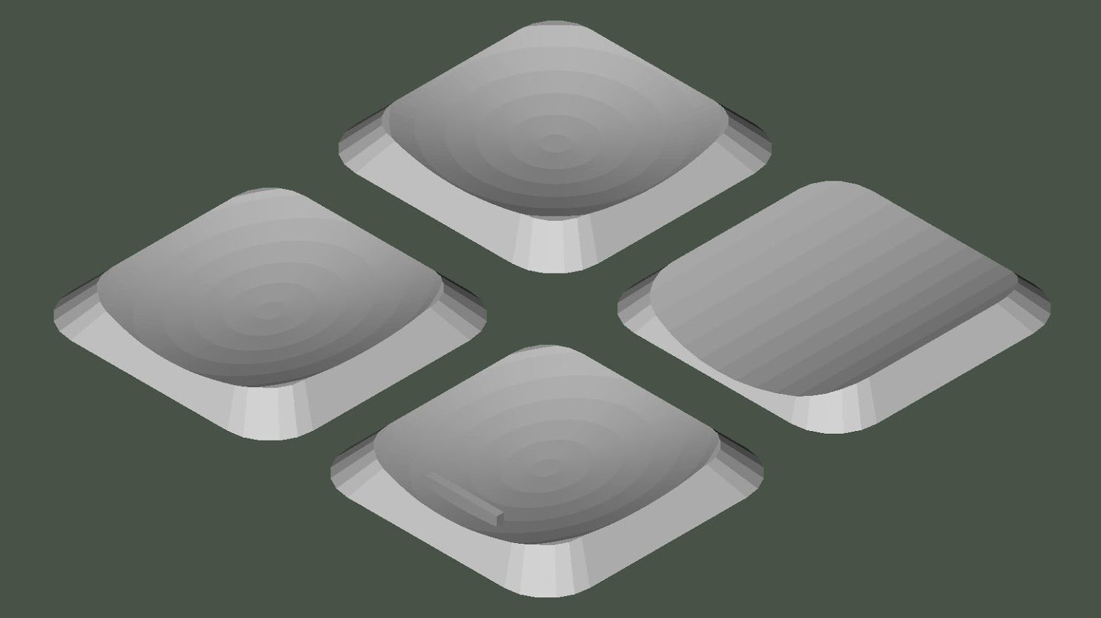
| Oh, it'll fit. Okay, maybe not a 3" load. |
The Shot Capsule
Now, I know they make shotshells in pistol cartridges, but they're expensive, the payload is miniscule, and the shot size is small. Supposedly you can even buy the caps to reload yourself, but they're also miniscule, expensive, and I have not witnessed them ever being in stock at any time I looked. So I think it's clear that those aren't what I want, so what do I want? I want to somehow find a simple and convenient way to load 44 SPL/MAG cartridges that will roughly duplicate a standard 410 load: 1/2 ounce of shot at 1100-1200 fps. It has to fit in this particular rifle, and its fitness for revolvers or other rifles is irrelevant. I tend to single-load cartridges anyway, so it doesn't need to actually feed through the magazine.
 |
| No. Just ... no. |
Now, I hope it's obvious that a half-ounce shot load won't fit into the SAAMI spec OAL for either 44 SPL/MAG. What's the actual OAL we have to work with? With this specific rifle, the maximum OAL which can be single-loaded into the chamber is about 2.15". At this length, an unfired cartridge cannot be ejected, striking the ejector before the cartridge fully clears the chamber. It needs to be manually unhooked from the extractor and tipped out of the action. At 1.75" OAL, the cartridge can be manually fed and loaded cartridges can be ejected. The longest OAL which can be reliably fed through the magazine is about 1.63", which is close to the SAAMI spec for 44 Magnum (1.610"). The payload constraint means that magazines and revolvers are simply not an option. The cartridge will actually have to extend well into the bore when chambered, and ejection is going to be slightly inconvenient.
 |
| A long cartridge strikes the ejector before it clears the chamber. |
The first thing that crossed my mind was to make a paper shot capsule. While I tried several variations of this, they were consistently inconsistent. It's a difficult balance trying to get something that will stay intact while handling, but will open up quickly, uniformly, and consistently. Rolling too many layers, using glue or tape, or tucking the ends too tightly would often delay the capsule from opening for about 2-3 yards. Considering that the target distance is about 3 yards, that's not acceptable. When the paper opened earlier, it would tend to unroll instead of tearing or breaking apart, creating a strongly asymmetric pattern. The paper patch/capsule idea still has some appeal and might be solvable. It has its simplicity and it's potentially a very accessible option. Who doesn't have a sheet of paper lying around? While the paper cartridges aren't terribly robust and are prone to spilling and getting kinked, that physical flexibility is a minor advantage. Since the paper capsule bends just a bit, you can snake a slightly longer cartridge into the chamber than you otherwise could with any rigid capsule. That might not seem like much, but bear in mind how pressed we are for volume with that payload constraint.
 |
| A paper cap in 44 SPL brass. |
That brings us to the solution. I had a small second-hand SLA 3D printer sitting on the shelf for nearly a year untouched because I didn't want to deal with figuring out the shitty OEM windows-only webapp-on-the-desktop slicer application for the poorly-documented and widely-unsupported unofficial design revision of the particular model I had (a late-model "original" AnyCubic Photon). I've used FDM 3D printers before, but I've always seen 3D printing as a severe compromise in terms of accuracy, surface finish, and material properties. Consequently, I rarely found a good reason to bother with the printer. While I hadn't used SLA printers before, I did expect the acrylic parts to be relatively brittle. I had some old expired clear resin that I got with the printer, so maybe this would actually be an appropriate use for it. After all, how else would I easily make a bunch of thin, brittle plastic cups?
 |
| Why do you assholes have to call every product model the same thing? |
Working off the dimensions gathered in earlier attempts with paper and other materials, I spent some time in OpenSCAD coming up with a cap geometry that would work. Since we're not injection molding these parts, there are a number of features we can afford that commercial caps can't. To ensure unifom breakup and resin drainage during printing, I slotted the parts. The caps can also have a uniform wall thickness with reentrant features like a base taper and cannelure. This gives us a few advantages: The base taper makes them easier to assemble into the case and it stiffens the mouth of the cap. The cannelure gives a bit better retention with less risk of cap breakage when crimping. The lack of mold draft means that the cap nose is less likely to survive intact and cause a defect in the shot pattern. Other than the hassle and mess of dealing with SLA printing, I think these features make the printed caps better than the commercially available caps. At the very least, they're available and customizable.
After a lot of trial and error, I had something that could be assembled, handled, and chambered with little risk of breakage, but would still reliably break up and pattern uniformly -- or at least as uniformly as you can expect from a shot pattern coming out of a fully-rifled bore. The design file is parametric, so features and geometry can be configured for calibers and applications other than my own. The nose geometry can be adjusted, whether you need a taper for easier insertion at max OAL, or whether you want a square nose for maximum capacity in a revolver. The zipper slots can be configured depending on how stiff you want the cap to be, though they do serve a purpose as drain vents during printing, and they aid in nose breakup, so it's probably not a good idea to eliminate them. The SCAD file optionally generates the parts on a raft. This helps with removing the fragile uncured parts from the build plate, and the attached label tag aids in incremental design refinement. The parts can be snipped off the raft with a pair of fine nippers.
 |
| Rafted parts and nippers |
 |
| Different size caps |
A word on the resin. Unlike nearly every other application, this is one case where we actually want our resin prints to be brittle. As time goes by, even the cheap resins will likely have improved toughness, so bear that in mind. It's preferable to stick with cheap, standard clear SLA resins. I'm currently using SUNLU standard clear green, though the original bottle I started with was a much older ERYONE standard clear that expired around 2019. There seem to be fairly wide margins on how tough the material can be before it causes breakup problems, but I'd stick with clear resins and thoroughly overcure them.
I should note that these clear resins can be dyed in a heated bath, so if you want to color-code your shotcaps (e.g. to denote the shot size or loading), you don't necessarily need multiple resins. I used my stock of old RIT dyes, though modern reformulated RIT will probably not work. You should be able to use iDye Poly without much issue.
 |
| Dyed caps |
Can these caps be printed with an FDM printer? Maybe, but I wouldn't bother. The design is more or less a nightmare stringing test for an FDM printer. You're trying to print a series of tall cylindrical and conical arc segments that are approximately one nozzle-width thick, with tiny gaps that are even smaller. Maintaining dimensional accuracy and stripping heat are going to be challenges. You could easily configure the SCAD file to produce a slotless cap and print it with a single wall. That might be easier, but it might not break up like we want. In the end, you'll get a part that's probably tougher than what you really want, and will likely smear and coat the bore due to friction and the relatively low melting temperature. The desire to make a brittle cap suggests that we should use something like PLA. You're free to try it, but I'm not interested in trying to find out how to remove a thin coating of solvent-resistant plastic from a rifle bore. Maybe there are exotic filaments that would work, but that's out of my capabilities. The acrylic resins are surprisingly resistant to heat, so SLA printed caps don't seem to be at significant risk.
The Wads
Now I haven't mentioned what goes under the shot column. That's because the wad is where everything starts becoming less ... satisfying. When I was originally playing around with paper caps, I was using something that I've used several times before -- starch packing peanuts. Not styrofoam peanuts, but the water-soluble packing peanuts. They compress into a tough, heat-resistant wad that will conform to the cartridge and bore with little issue. I have found them to be surprisingly effective for doing dumbass weird shit like this. That said, they're tedious to install and compress, they need to be fairly thick to work, they're limited in the amount of heat and pressure they can take, and they're inherently inconsistent. With a rigid cap, the maximum allowable powder+wad stack height demands a dense powder and a short wad. While moderate for the rifle, the developed pressures are still too much to reliably withstand at an appropriately short wad thickness.
 |
| Fired peanut wads |
I thought about printing plastic wads, but considering the brittleness of the material, and the fact that I didn't want a bunch of significant chunks of plastic trash all over the place, I didn't pursue the idea. I also wasn't really too keen on having powder stored in contact with questionably-cured SLA resin and potentially turning all sweaty and weird. The long-term compatibility of powder and resin is something I'd want to test experimentally before I'd use it, and that would take a long time to test.
Instead, I just made a primitive punch and die out of scrap from the trash pile, just to see if paper wads would work or not -- a proof of concept. I'm using 0.058" thick card stock (some used presentation boards). Call that 500lb cardstock or a 60pt mat board. Translating that into the conventional ill-standard "ply" units is pure guesswork, so good luck shopping. With a die diameter of 0.425" and a concave punch face, the wads come out around 0.429-0.430", which is a nice snug fit in sized brass. For most loads, I use 3 cards for a wad height of 0.175". With this heavy card stock, I can get by with 2-card wads, but I wouldn't try to replicate such a thin wad with more layers of thinner stock.
 |
| Using the lathe tailstock as a simple screw press |
 |
| Wads, wad insertion tool |
The cardstock wads work well, though I dislike the fact that the wads or punch aren't something that can be easily obtained. They aren't a standard size, so you're not going to be able to buy a tool set or precut wads. Even the rudimentary die set I made required a lathe to make. A press-mounted punch would be more complicated, and like most practical problems, it's well out of the capabilities of pedestrian 3D printing, so maybe it's not as accessible as I would have liked.
EDIT: In recent efforts, I have actually found that there are appropriate card wads available for 38/44/45 applications. In 44, I'm using a 0.175" wad stack, but a single 0.125" nitro card should be totally adequate. The wad thickness difference can be compensated for with a simple change in the SCAD file.
Ballistic Products
Track Of The Wolf
UPDATE: I have been toying with wads printed from PLA and stiff (98A) TPU. The TPU wads are nice in that they're compressible enough to produce a nice tight fit in the case, which should improve consistency with slower powders. As mentioned, printed wads aren't an option for resin. Not only are they too brittle, my initial tests suggest that the resin will not be powder-safe. The models for the printable wads are posted here:
on Thingiverse
on Printables
I also included a press-mounted wad setter which makes everything easier and more consistent, whether using printed wads or the regular card stacks.
The Powder
I also haven't mentioned what powder I used. Well, that's where things are even less ideal -- at least for me. It's fair to say that this entire project is not something you're going to find load data on in any book, but we could always look at the nearest neighbors. I use Herco for 44 SPL plinking loads: 240gr @ ~1030 fps with 7.0gr, or 1125 fps with 7.5gr. That's not too far off-target, considering that 1/2oz is roughly 220gr. Surely the slightly lighter payload would push us a bit higher in the velocity? There's a couple problems with thinking that these pistol powder loads are going to be comparable or usable. First off, Unique and Herco are just too bulky to be viable. Second, there's no tight crimp, neck tension, or engraving force, so early pressures are low and the actual powder efficiency is low. The same charge that gets over 1100 fps out of a 240gr bullet barely makes over 900 fps with a lighter payload, leaving behind lots of sticky unburned residue.
What else is on the shelf? Circa 15gr of H110 might be appropriate for an actual 410 load, so what's wrong with that? It's really the same story. That large charge of H110 eats up the available stack height really fast, and is still on the borderline of being underpressured. It seems that 410 loads are probably at the lower end of the pressures that H110 likes to burn properly. The shift to a slightly larger bore diameter is probably just enough to push us close to the hairy edge of having occasional poppers and barrels full of yellow unburned powder grains. H110 is simply inappropriate for lighter (i.e. SAAMI spec-length) loads, though perhaps those could work with the pistol powders.
I don't have a lot of powders on hand, and my LGS hasn't had much of any powder (or anything) on the shelf in the last three years. I'm sure there's something that's more dense than Herco, while being able to perform at relatively low chamber pressures. I could throw a dart at a burn rate chart and try something blindly, but I hate gambling on components if I know I don't have an alternative application for whatever I'm buying. Besides, I do have this ancient can of Alcan AL-7.
 |
| Sketchy? Pff. It'll be fiiine. That rust is just part of the aesthetic. |
With 12.0gr of AL-7, 2 card wads, I can barely fit everything within 2.15" OAL. The result is 220gr of shot at 1215 fps. A 10gr charge puts us just under 1100 fps, which at 3-5 yards isn't really that much of a loss, but it gives us more wiggle room on stack height. I've settled on 10.5gr and 3 card wads. That's a bit on the low end of what I'd call a 410-equivalent load, but considering how severely the rifling limits the effective range, there really isn't much point in pushing the velocity too far anyway.
So AL-7 works great. It's dense enough and tolerates the low pressures just fine, but nobody will be able to use this load data because AL-7 hasn't been on the shelves in 40 years. It's going to really suck when I run out of AL-7, but maybe if you're more familiar with similarly dense powders in this part of the spectrum (e.g. AA#5, HS-6/W540, WSF, Longshot, etc), you'll be able to use this suggestion as a data point in finding a suitable replacement.
Conclusion

 |
| Obligatory glamour shots |
So in the end, I have what I think is about all I really need from the cartridge. It's roughly equivalent to a moderate 2-1/2" 410 load, but I can use it in a short, handy rifle that's also usable for other things. They sound good, feel good, and I'm getting fond of the smell of AL-7. They produce about a 6" pattern at 3 yards, and the cap breakup is uniform. Setback dictates that the nose of the cap is never really subjected to any hoop stress as the shot column is upset, so the largest cap fragments tend to be from the nose. Since the cap is slotted, those fragments are never large enough to disturb the patterning (at least not with the #6 shot I'm using).
 |
| Cap fragments captured in a deep box of loose paper |
While the loaded cartridges are durable enough to handle or put in a pocket, they aren't a 410 hull. If you drop them on concrete, they'll likely break and spill. It's easy enough to pick the rest of the cap out of the case mouth, expand the neck, and install a new shotcap without wasting the other components. I don't know if that's even practical with commercial caps, since they use a snap-in plastic base wad.
Preferred:
Remington LP primers
10.5gr AL-7
3 card wad (0.175")
one 215L cap full of shot (approx 220-230gr)
a bit over 1100 fps
Full power:
Remington LP primers
12gr AL-7
2 card wad (0.117")
one 215L cap full of shot (approx 220-230gr)
a bit over 1200 fps
Size and prime, expand the mouth if desired, charge the cases, and ram the wads. Fill a shot cap like a cup and gently press the loaded case on top. Crimping just requires the removal of the bullet seater (if you use a seat+crimp die). Contrary to what I've read about the blue caps, I don't ever have issues with breakage during crimping, only during seating. Work over a pan, because you'll probably break a few caps along the way. Shot spilled in a pan is a lot less of a mess than shot spilled in the press.
If you want to play around with different powders, you might need to adjust the cannelure position or cap length as necessary for your stack height. For perspective, 10.5gr AL-7 is approximately the same compressed volume as 9.0gr of Unique or 8.3gr of 700x. All of these loads will work with the same wad stack and shot cap, so if you want to play around with unsuitable pistol powders, that's one place to start. For what it's worth, both of those charges do work. The Unique load runs about 1100+ fps, but burns poorly. I forget the velocity for the 700x load, but it's hard on wads and the shot column, so expect pattern degradation. On the bright side, at least there's plenty of margin on max pressure when working in 44 magnum.
The SCAD files are up on Thingiverse and Printables.
EDIT: I've come to discover the existence of early pre-410 cartridges such as the 44XL. The 44XL was basically a 44-40 with a paper cap and an overspec ~2" OAL. So I basically reinvented a cartridge concept that died out a century ago. I suppose if anyone wants to load 44XL, these caps would work great for that as well.
I also see bastard 45LC/410 chamberings in things like the Taurus Judge and Rossi Brawler and I have to cringe at the notion. I haven't seen a dimensioned chamber drawing, but I imagine it's the worst of both worlds. You get to shoot 45LC with a bunch of freebore for maximum leading, and you get to shoot 410 out of a grossly oversize rifled bore for terrible powder efficiency and patterning -- all because garbage laws force us into these compromises. That said, if you want to get more payload into a Brawler, an oversize cap in 45LC brass should at least be able to get more lead into the pattern. That's probably going to be way more effective than wasting money on 410 in such a pistol.
 |
| All of these shot caps will fit on top of the same powder+wad stack. |