After eventually swapping the monitor with a spare, I stripped it for disposal and salvage. I took another look at the cathode driver board just to see if the audible failure came from any of the IC's. I clipped the main driver IC off the board and decided to take a closer look.
 |
| SHW3528 cathode driver hybrid IC (leads clipped off) |
Right away I became suspicious. With my terrible eyesight, I hadn't noticed before that this wasn't a typically encapsulated package, but a custom hybrid IC. I know it's only anecdotal, but I doubt I have encountered such a device that wasn't a problem or didn't experience a packaging-related failure (shakes fist at those goddamn STK3122's). The device was mounted with heat sink compound, though the compound was rather petrified. I popped the cover off and had a look inside.
 |
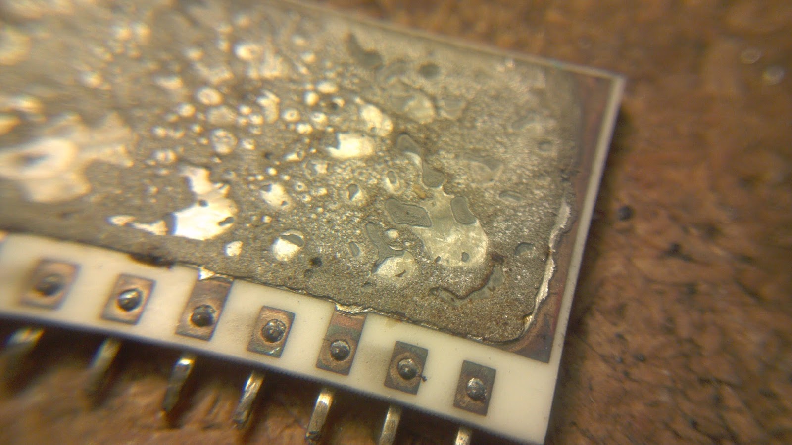
| Snapped substrate and fractured attachment solder |
The ceramic substrate broke when I removed the cover. This pretty much reveals the root cause of failure. From left to right, the associated channels are green, red, blue. The progressive degradation was due to a failure of the substrate attachment to the thermal tab. This appears to be a reflowed high-tin solder, and was clearly fractured and corroded. The only part of the substrate remaining firmly attached to the thermal tab is the blue channel. As a rough guess, I'd say that there was maybe 20W or so intended to go through that thermal interface. I can only imagine how hot the substrate and junctions were operating
 |
| That's your thermal path. No really! |
 |
| That is some ugly shit. |
Although by the time I bothered to take pictures, the bond wires had seen a thumb or two, the dice in the red channel are clearly marked with craters indicating their failure. Whether the sudden failure of the red channel was induced by the board removal and reinsertion is unknown but likely.
 |
| Two rightmost dice of red channel showing (blurry) cratering |
So there, the substrate attach had fractured and the thermal path was compromised causing an asymmetric degradation of the device channels. It can't be seen from the photos, but the plating on some of the leads is coming off and the metal is heavily tarnished underneath. It's easy to just say that thermal cycling caused the fracture, but I'm rather certain that there are some issues of metallurgical nuance to be blamed as well.
Hello mate nnice blog
ReplyDelete